EECS 140 Square Wave Oscillator
Simple Square Wave Oscillator
Objectives
- A. Construct a simple square wave oscillator on your lab board
- B. Learn to use an oscilloscope to observe and measure electrical signals
This exercise will run two weeks. The first week you will construct the oscillator and the second week you will learn to use an oscilloscope. Construction of the oscillator is described in this document, called Exercise 2.1. Use of the oscilloscope and experimentation is described in a separate document, called Exercise 2.2. The oscillator you build in this exercise will be used on most future exercises.
Discussion
In this exercise you will construct an oscillator which generates a square wave output. That is, the output will be a "high" voltage (about 3 volts) for a short period of time and then a "low" voltage (about 0 volts) for about the same amount of time.
The oscillator is built from a pair of multivibrator circuits. A multivibrator works in the following way: when it detects an input going from high to low, the output of the multivibrator goes high for a short period of time and then goes back low again. The period of time the multivibrator output is high is determined by the values of a resistor and a capacitor.
Now, if we connect the first multivibrator output to the input of a second multivibrator, the output of the second multivibrator will go high for a short period of time just after the output from the first multivibrator goes from high to low (at the end of the "high" time period). And if we connect the output of the second multivibrator to the input of the first, the first multivibrator will be triggered and the cycle will repeat. We have an oscillator.
Figure 1 illustrates the outputs of the two multivibrators. At time A #1 is triggered and the output is high for three time units. At time B, the output of #1 goes from high to low triggering #2. The output of #2 is high for three time units. When the output of #2 goes from high to low, #1 is triggered again (time C) and #1's output is high for three time units.
2.1 Background information on components
You will build your project from parts provided by the EECS Shop. You'll receive the base printed circuit board and the components needed for this exercise. Many will not be familiar with electronic components, so we'll describe those components here.
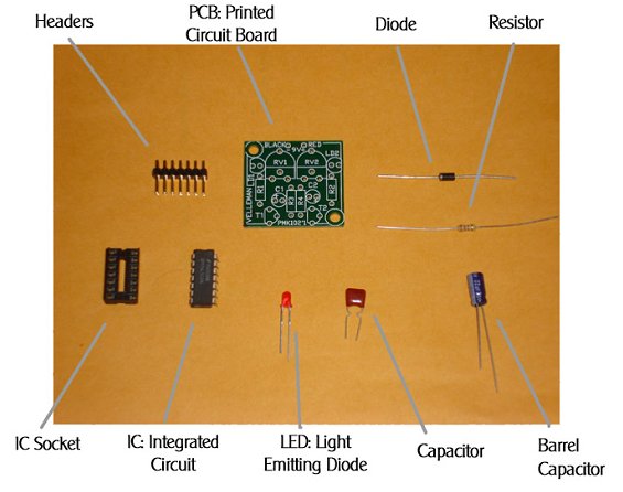
Figure 2 show the component types you will use to build your project. We will discuss each of these components starting with the IC Socket and continuing in a clockwise
fashion.
Headers
Headers will be used to make simple connections, test points, and configure the project for different exercises. Headers are small pieces of plastic that can be connected together using jumpers. You will get them either in strips that are two posts wide, or a strip a single post wide. You break the strips to desired length using pliers. When you insert posts into your circuit board, insert the shorter end into the board for soldering.
To connect headers, you can either you use jumpers to short them. We will be using jumpers to connect headers together throughout the semester.
Printed Circuit Board
PCB’s are the boards in which you will insert electronic components to on the top side, and then solder them into place on the bottom side. The example shows a simple PCB with labeled component locations, but in general they will not include them. PCBs are meant to be used with clamps, so as to grip the PCB in place while your hands are working on soldering.
Diode
The Diode looks similar to the resistor, but in our case the diode has a black body. The diode allows current to flow in one direction, so it is like a one-way street. To indicate the direction of current flow, the diode has a white band towards the end the current will flow toward, we think of this as the "pointy end" of the direction arrow. Notice that the white band is actually printed into the component itself, and not the packaging around the wire ends.
Resistors
Resistors, as their name implies, resist the flow of electrical current. With a large resistor, little current flows. A small resistor, a larger current flows. The resistors we'll use are light brown in color with four color bands. The resistor body is about 1/4" long with axial component leads. Resistance is measured in Ohms, named after George Ohm who worked on electricity problems in the early 1800's. We sometimes denote Ohms with the uppercase omega symbol, Ω.
The color bands indicate the resistive value of the resistor. Each color corresponds to a digit. The first two digits (colors) are the significant digits, the third digit indicates the exponent (or order of magnitude), and the fourth digit indicates the precision. The correspondence between colors and digits is given in Table 1.
Table 1 lists the resistor color code. The fourth color band is either gold, indicating +/- 5% precision, or silver, indicating +/-10% precision.
The resistor value is computed with the following formula:
Resistor Value = D1 D2 x 10D3
So, if we have a resistor with the first band Green, the second Brown, and the third Orange, the value would be 51 x 103 Ω, or 51,000 Ω, or 51 kΩ. If the colors were Purple, Green, Red we would have 75 x 102 Ω, or 7.5 kΩ. Note that you can determine at which end to start reading the resistor code because the precision colors are exclusive of digit colors.
You will need to read the resistor color code because we will refer to resistors by their values.
Capacitors
Capacitors are used to store electrical charge. They act as a "storage tank" for electrical charge. When the voltage across a capacitor increases, more charge moves into the capacitor. When the voltage across a capacitor decreases, charge flows from the capacitor back into the circuit. Capacitors work to buffer or moderate swings in voltage. Capacitance is measured in units of Farads, named after Michael Faraday. A 1F (one Farad) capacitor is very large and more typical values you will encounter in class are less than a microFarad, denoted µF
For large barrel capacitors, values are plainly printed on them, such as 50 µF (Fifty microFarads). However, for disk and plastic film type capacitors there is generally room for a number code. If there are just two digits, the digits indicate the capacitance in picoFarads (pF). A pico-Farad is 10-12 Farads.
If there are three digits, the numbering scheme is similar to the resistor number code. Digits 1 and 2 are significant digits, and digit 3 is the multiplier code. Usually the last digit provides the number of zeros to write after the first two digits. Table 2 shows the multiplier code.
| Multiplier Code | Multiplier |
|---|---|
| 0 | 1 |
| 1 | 10 |
| 2 | 100 |
| 3 | 1000 |
| 4 | 10000 |
| 5 | 100000 |
| 6 | Not Used |
| 7 | Not Used |
| 8 | 0.01 |
| 9 | 0.1 |
For example, a capacitor marked "223" would have a value of 22,000 pF or 0.022 µF while a capacitor marked "104" would have a value of 100,000 pF or 0.1 µF.
Light Emitting Diode
The Light Emitting Diode or LED is a diode but constructed in such a manner that light is emitted when a current is passed through the LED. LED’s use little power and, great for indicators, and highly reliable. The LED we install in this exercise is used to indicate that power is applied to the project. Note that the LED has a portion of the base "shaved" off or it contains a notch. This flat or notched part indicates polarity of the LED similar to the white band on the diode. It will be important to pay attention to this flat part when installing the LED.
Integrated Circuit
Integrated Circuits are packaged inside a rectangular piece of black plastic. Connections to the circuit inside are made through metal leads. ICs may have as few as 4 leads or as many 500 depending on the package. The ICs we will deal with will have 14, 16, and 24 leads and the lead, or pins, are arranged in two rows. Hence, the IC package is many times referred to as a dual in-line package, or DIP.
ICs have a code stenciled on their top indicating the type of the IC. A typical code might be "74LS123". The "74LS" indicates the family of the IC. The "123" indicates a specific type, in this case a dual (i.e. two) multivibrator.
ICs also have an orientation. Usually there is a semi-circular cut in one end of the IC or a small, round dimple towards one end and to one side. Figure 3 illustrates these orienting features.
Figure 3 also illustrates how pins are number on ICs. Once you locate the cutout or dimple looking from the top, Pin 1 is on the upper left. Pins are numbered sequentially down the left side of the IC, then from bottom to top on the right side. For the ICs we will work with the lower-left pin (Pin 8 in the diagram) is the Ground pin and the upper-right pin is the Power pin (+5 VDC).
Integrated Circuit Sockets
The Integrated Circuit Socket, or IC Socket, is used to hold integrated circuits (ICs). Soldering the socket into the board and then inserting ICs into the socket allows one to quickly change the IC should that be necessary. IC Sockets are plastic with metal pins embedded. The one I have is blue plastic, but you might encounter other colors.
Tools and Components
Check-out the following tools and components from the EECS Shop:
- A. A pair of goggles
- B. A handheld soldering iron
- C. A pair of wire cutters
- D. A pair of needle-nosed pliers or forceps
- E. A soldering sponge
- F. A digital lab kit
Tasks
Each person should build their own project board and carryout the following tasks. However, it suggested you work in pairs so that one person reads the instructions while the other person works on their board. You should completely read through each step before executing that step.
Quiz
The quiz for this lab will be included in the second part (Oscilloscope Use). Come prepared next week with your answers!
Step 1 – Preparation
Checkout the required tools and parts from the EECS Shop. Plug in your soldering iron to warm it up. Wet your soldering sponge.
Step 2 - Build the power connection section
- Identify the top of your PCB. When viewing the top of the PCB, the area with hundreds of holes in a regular pattern should be towards you on your bottom right. The power section is built in the upper-left corner of the PCB.
- Pick out the following components: Red/green LED, R30 (270 Ω) resistor, wirewrap posts (4 posts long), wirewrap posts (2 posts long), and the diode. You may have to cut the wirewrap posts to the desired length. Keep the remaining part of the wirewrap post strip as you will need those posts later in the exercise and the project.
The components will be inserted into the PCB as indicate in Figure 4.
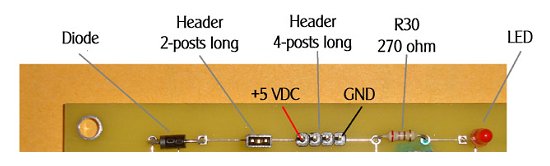
Identify the flattened side of the LED base. Identify on the PCB the position of the LED. With the flattened side of the LED pointing left, insert both leads of the LED through the holes on the PCB in the indicated location. The LED should be inserted completely so that the bottom of the LED plastic lens is seated on the PCB. Flip the PCB over and solder the two LED leads into place. Use the diagonal cutters to trim the excess leads from the LED. The remaining leads should less than 1/8".
Identify R30, a 270 Ω resistor. Using the long-nosed pliers, bend each lead about 1/8" from the body of the resistor. You should hold the lead with the pliers and bend against the pliers. The pliers protect the body of the resistor from breaking when you make the bend. Insert the resistor into the top side of the PCB in the position shown, flip the PCB, solder in R30, and clip the leads.
Using the pliers, break a header four (4) posts long from the strip. Insert the short end of the header into the PCB in the position shown and solder in place. You do not need to clip the header. These four posts are for power supply connection. Ground will be connected on the rightmost post and +5 VDC (power) will be connected to the left-most post.
Cut a header two (2) posts long from the strip and insert in the position shown and solder into place. These two posts are a simple on/off switch. For this exercise you must short these two posts together with a jumper to apply power to the circuit
Identify the diode and locate the end with the white band. The white band does not refer to the stickers attached to the leads, but the band on the component itself. Bend the leads on the diode by holding the leads at the body with the long-nose pliers. Insert the diode into the PCB at the position shown with the white band to the left. This diode protects you project should you accidentally connect power incorrectly.
Step 3 - Initial power-up test
Have the GTA take a quick look at your construction of the power-supply section. Check for good connections, no solder globs, and no shorts between pins. If everything is OK, you're ready to apply power.
Make sure the power supply is turned off and the dial is set to the 5V position.
From your lab kit pick out a banana plug to BNC adapter and a BNC to E-Z Hook cable. You may find these already hooked together. If not, connect the cable to the adapter. Insert the adapter into the power supply. The power supply has two banana plug posts, a red post and a black post. The adapter could go in two ways, but we need to make sure we get Ground from the power supply connected to Ground on the PCB. On edge of the adapter is a tab. The tab side indicates the Ground side and should be inserted into the Black post on the power supply.
At the other end of the cable are two E-Z-Hooks, one red (indicating power or +5 VDC) and the other black (indicating Ground). Connect the black hook to the rightmost post of the 4-post header strip; connect the red hook to the leftmost post of 4 post strip. Double check that the power supply is set to 5 VCC, and turn the power supply on. Check for smoke, hopefully none, and that no component (R30, Diode, or LED) is too hot to touch and the red LED lights up.
You've powered your first project circuit.
Turn the power supply off and disconnect the E-Z Hooks from your PCB.
Step 4 - Building the oscillator timing section
The next section we will build controls the time each multivibrator outputs a high voltage. This section is designed to support several different times, so we'll be inserting a few more components than we'll use in this exercise. Figure 5 shows this section of the PCB and the components we'll be inserting.
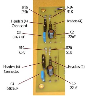
Insert resistors R15, R16, R19, and R20 in the locations indicated. R15 and R19 are 7.5 kΩ resistors and R16 and R20 are 51 kΩ resistors. Bend the leads, insert, flip the PCB, solder, and clip the leads. You can probably do all four resistors as a batch.
Insert capacitors C2, C3, C4, and C6. C3 and C4 are 0.027 µF capacitors and C2 and C6 are 22 µF capacitors. Note C3 and C4 might be small, brown capacitors, not the round cylinders like C2 and C6. Insert the capacitors, flip the PCB, solder, and clip the leads. You can probably do all four capacitors as a batch.
Cut 4 segments of headers, each 4 posts long. Insert the headers in the locations indicated and solder in place.
To connect the resistors and capacitors to the rest of the oscillator circuit, you need to make connections between the four posts of two left most sets of header strips as indicated on the left side of Figure 5. Use jumpers to accomplish this.
Step 5 -- Multivibrator section
The final section to construct is the multivibrator itself. Figure 6 illustrates this section of the PCB.
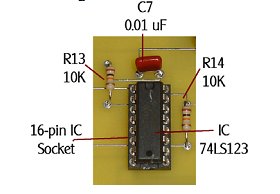
Figure 6 shows the multivibrator IC in a socket, two pull-up resistors and a place for a bypass capacitor.
Locate R13 and R14, both 10 kΩ resistors, and C7, a 0.01 µF capacitor. Insert in the locations indicated, solder, and clip the leads.
Locate the 16 pin IC socket (blue). Insert into the PCB, flip the board, and solder all 16 pins. These pins are tight, so use little solder and make sure you do not short two pins together. Insert the 74LS123 chip into the IC socket with the cutout towards the power connector.
Finally, about 1" to the right of the IC socket are 5 holes in a sideways "T" arrangement. Insert a 2-post long header strip into the leftmost two holes (horizontal) and solder in place. This is the output of your oscillator.
Step 6 - Testing your circuit
Have the GTA visually inspect your work for obvious problems. Reconnect your project to the power supply as described above and turn on the power supply. The LED should light and no component should overheat or smoke. Good!
For this part of the exercise we will perform a few simple tests. Part 2B will introduce you to the oscilloscope for more extensive tests.
Locate the Logic Probe in you kit. The logic probe is a simple device for checking the voltage levels of pins in your circuit. The logic probe has a cable with two E-Z Hooks at the end, a red one and a black one. Connect to red to the +5 VDC (power, leftmost) post of your power connector and the black to the Ground (rightmost) post of your power connector.
Touch the tip of the logic probe to pin 8 (lower left corner) of 74LS123. It should indicate a low signal. Touch the tip to pin 2 of the 74LS123. It should indicate a high signal.
Use the oscilloscope probe on the test point you soldered last (left header). Press 'Auto Scale' on the oscilloscope to visually see the square wave in the monitor. If you get this, your board is working. If not, contact the GTA for help or read Exercise 2.2 to learn about the oscilloscope.
Step 7 - Clean-up
When you've completed you lab session, gather the tools you've checked out from the EECS Shop and return them to the shop. Clean up your work area of wire scraps and insulation and throw away. Take your project board and extra components with you, but remember to bring them with you to your next lab session.
Laboratory Report
You do not need to write a lab report for Lab 2.1. A lab report will be written for Lab 2.2 covering both exercises.